The valve gear on the 812 Class was operated by Stephenson's
Link gear with locomotive links. It operates slide valves arranged vertically
between the cylinders. The cylinders and steam chests are based on the design
used in the Dunalastair II express passenger 4-4-0s.
The pistons used in the 812 class were made of cast iron. The piston rods and
crossheads were one-piece steel forgings. The slide bars were of the closed type
and McIntosh used his own method of fixing the front of the slide bars directly
to lugs on the cylinder casting. At the rear the slide bars are supported by the
motion plate which also acts as a substantial frame cross-stretcher.
The connecting rods used by McIntosh on the 812 class were
single piece forgings with marine-pattern big ends. The big end bearings were a
bronze alloy lined with white metal and drove onto generously sized crankpins of
8 inch diameter.
The axle journal diameter specified for the 812 class was 8
1/2 inches. The axlebox bearings were manufactured as bronze castings with white
metal bearing surfaces.
Lubrication to bearing surfaces was assured in a number of
ways. A sight-feed lubricator in the cab provided lubrication to the steam chest
for the valves and pistons. A pair of Furness lubricators mounted on the front
of the smokebox provided additional lubrication to the cylinders when the
regulator was shut. Lubrication of all other moving parts was provided from
individual oil reservoirs and controlled by worsted trimmings.
One of the developments
that McIntosh took advantage of was an improved understanding of the importance
of providing a very free passage for the escape of exhaust steam from the
cylinders. In the picture below we can see how the steam chest was mainly placed
above the centreline of the cylinders. This reduced the tendency for stifling of
the passage of exhaust steam from the lower half of the cylinders on designs
where the steam chest centreline coincided with the cylinder centreline. Raising
the steamchest also allowed larger diameter cylinders to be used within the
narrow confines of the frames - an important consideration for an inside
cylinder design.

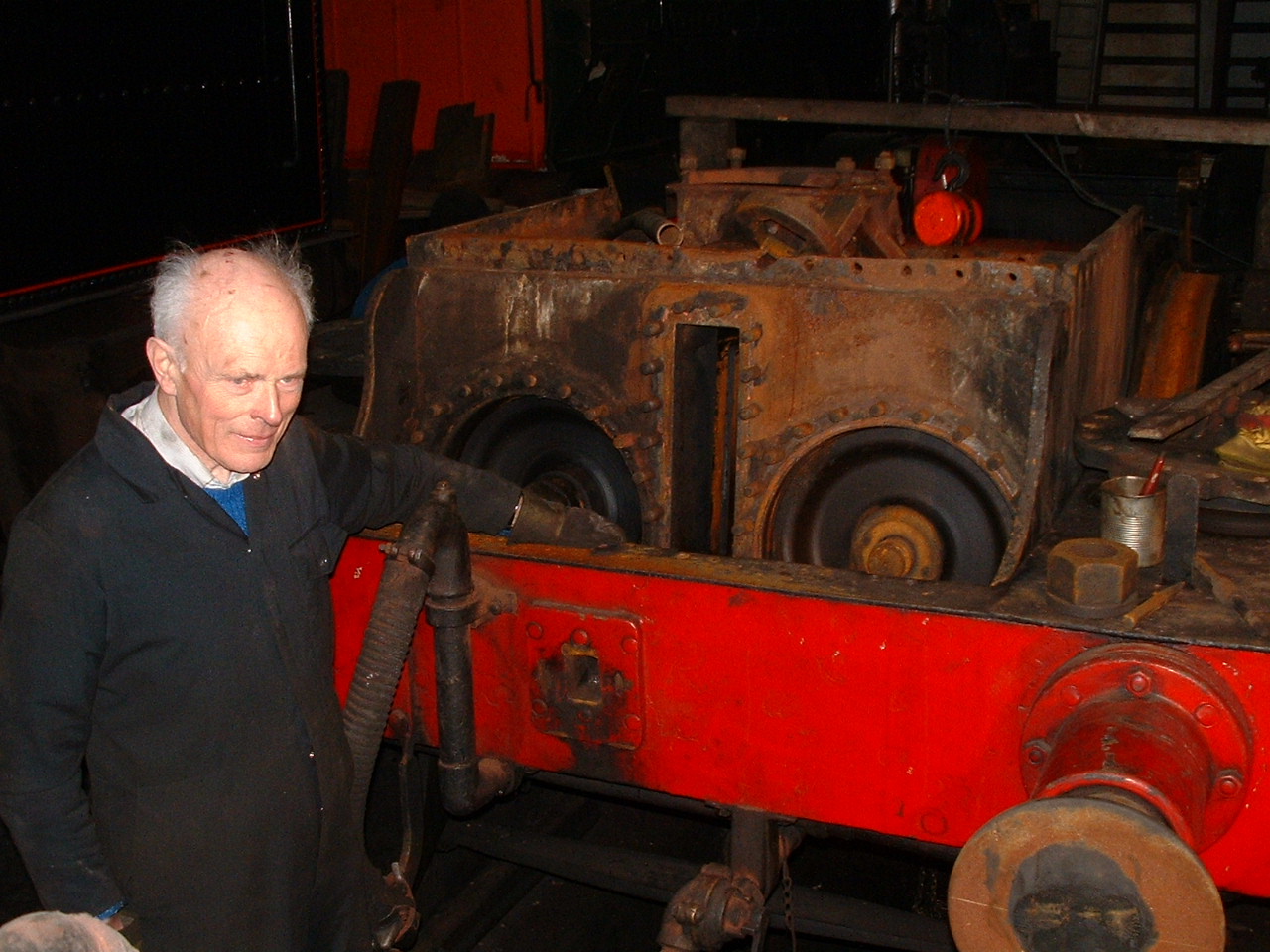
In this view we see Project Engineer Graham King standing
by 828's front buffer beam. The cylinder block is immediately behind. Both
cylinder covers have been removed and the pistons can be seen lying towards the
front of their stroke. The steamchest cover (between the cylinders) has been
removed and the slide valves which control the admission and exhaust steam have
also been withdrawn.
.JPG)
In this picture we can see inside the steamchest. The ports
which allow steam admission and exhaust from the front of the right hand
cylinder can be seen. By raising the steamchest above the cylinder centreline JF
McIntosh allowed the exhaust steam to escape freely from the cylinders. This
allowed more power to be developed in the cylinders compared to the earlier
practice of arranging the steamchest on the same centreline as the cylinders.