Inside the Boiler
Access to the inside of the boiler is gained through the dome cover opening.
The Dunalastair boiler has four longitudinal stays which connect the smokebox
tubeplate with the firebox throatplate. By good fortune (or clever design) these
are pitched far enough apart that they can be sprung slightly to allow a person
of average size to slide through and get into the boiler barrel. The pictures
below show what the inside looks like.

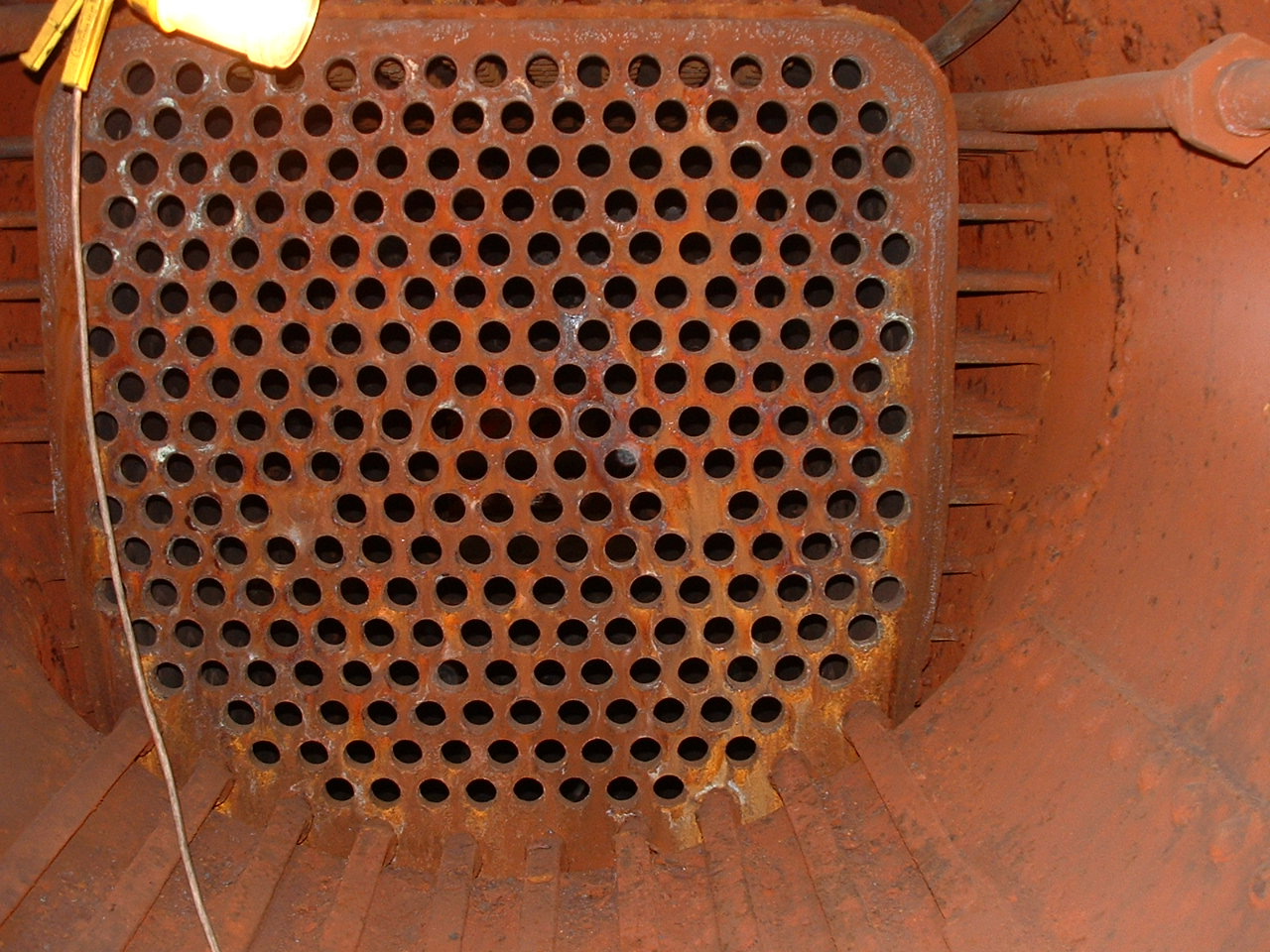
In this picture we are looking from the middle
of the barrel towards the firebox throatplate. The 'honeycomb' structure is the
inner firebox throatplate. The holes are normally filled by the boiler tubes.
The inner firebox is made of copper plate and is attached to the outer firebox
by a series of 'stays'. Some of the sidestays can be seen on either side of the
picture. The ten palmstays can be seen in the bottom of the picture.
Approximately one third of the way up the right hand side of the picture the
line of rivets marking the top edge of the 'doubler plate' can be seen.

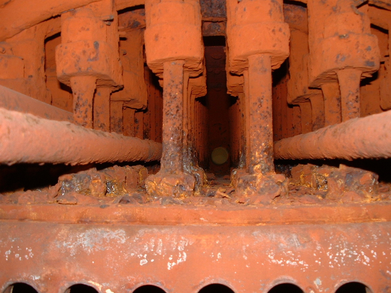
In this picture we are looking along the top of the inner
firebox. The vertical bars are the firebox roofstays which connect the outer
firebox and the roof of the inner firebox. The stays are a combination of
'sling' stays which allow a certain amount of flexibility and 'direct' stays
which are more rigid.
.JPG)
This picture shows an identification number
stamped into the inner firebox. The number (57642) belongs to a locomotive in
the same class as 828. So has our engine been running with the inner firebox
from a long-scrapped classmate or is it a works part number?

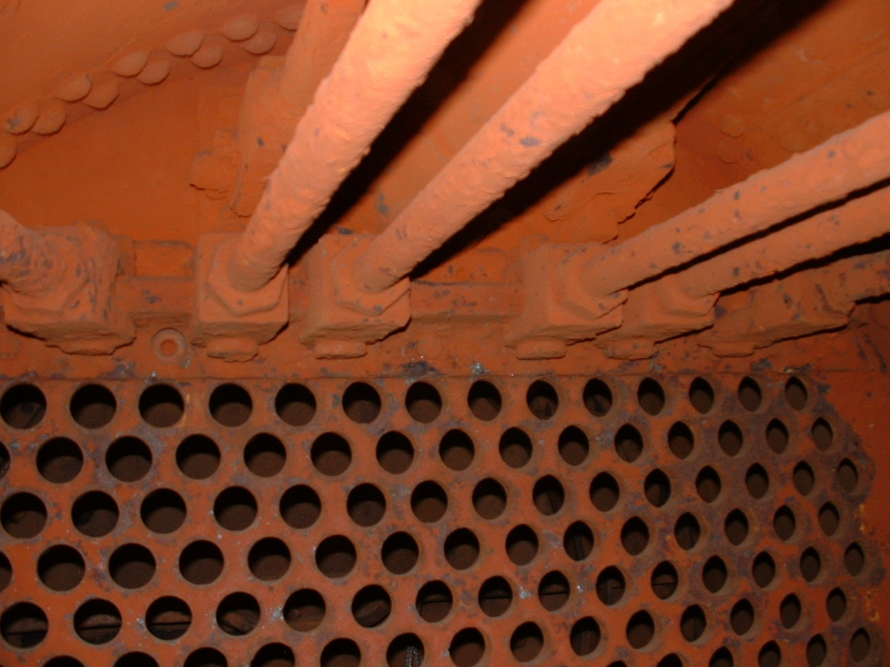
Here
we see the front end of the boiler from inside the barrel. In this picture we
can see the smokebox tubeplate and the complex system of staying used by JF
McIntosh in the Dunalastair boiler. In the centre are the four longitudinal
stays which connect the smokebox tubeplate and the firebox outer wrapper
backhead. The side
and top stays which connect the smokebox tubeplate directly to the boiler barrel
can be also be seen. It is interesting to see that the connections are made by
'pin and clevis' joints which allow a great deal of flexibility and undoubtedly
reduce the stresses experienced by the boiler during heating and cooling.